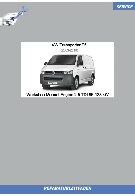
VW Transporter T5 (03-09) Workshop Manual Engine 2,5 TDI 96-128 kW
| eTitel | VW Transporter T5 (03-09) Workshop Manual Engine 2,5 TDI 96-128 kW |
|---|---|
| Seitenzahl | 197 |
| Artikelzustand | Neu |
| Artikelart | Reparaturleitfaden |
| Behandelte Reparaturgruppe | Motor |
| Sprache | Englisch |
| Druckvariante Printversion | Printversion in S/W |
| Druckvariante Ebook | Ebook farbig |
| Hersteller | VW |
| Modelle | VW Transporter 2004 ➤ |
| Typ | 7J, 7H |
| Baujahre | 2003 - 2009 |
| Verlag | TEC VERLAG GmbH |
| Leistung kW / PS: | 131, 163, 174 PS / 96, 120, 128 kW |
| Motorkennbuchstabe | AXD AXE BLJ BNZ BPC - 5-cylinder diesel engine |
| Hubraum | 2,5 Liter |
Repair Group
00 - Technical data
10 - Removing and installing engine
13 - Crankshaft group
15 - Cylinder head, valve gear
17 - Lubrication
19 - Cooling
21 - Turbocharging/supercharging
23 - Mixture preparation - injection
26 - Exhaust system
28 - Glow plug system
Contents:
00 – Technical data
1 Identification
1.1 Engine number/engine data
2 Safety information
2.1 Safety precautions when using testers and measuring instruments during a road test
2.2 Safety precautions when working on the cooling system
2.3 Safety regulations for working on fuel supply
2.4 Safety precautions when working on injection system
3 Repair instructions
3.1 Rules for cleanliness during work on fuel system
3.2 Rules for cleanliness when working on fuel supply system
3.3 Rules for cleanliness when working on injection system
3.4 Foreign objects in engine
10 – Removing and installing engine
1 Removing and installing engine
1.1 Removing engine
1.2 Securing engine to assembly stand
1.3 Installing engine
2 Assembly mountings
2.1 Assembly overview - assembly mountings
2.2 Removing and installing front torque reaction support
13 – Crankshaft group
1 Cylinder block (pulley end)
1.1 Assembly overview - crankcase
1.2 Crankcase - attachments
1.3 Removing and installing sealing flange on pulley end
1.4 Renewing seal for timing housing cover
1.5 Renewing alternator shaft oil seal
1.6 Removing and installing thread insert for tie bolt
2 Cylinder block, gearbox end
2.1 Assembly overview – valve timing housing cover
2.2 Removing and installing drive plate
2.3 Removing and installing flywheel
3 Crankshaft
3.1 Assembly overview - crankshaft
3.2 Basic settings for gear train
3.3 Crankshaft bearing cap identification
3.4 Crankshaft dimensions
3.5 Measuring axial clearance of crankshaft
3.6 Measuring radial clearance of crankshaft
4 Pistons and conrods
4.1 Assembly overview - pistons and conrods
4.2 Installation position and allocation of piston to cylinder
4.3 Measuring piston projection at TDC
4.4 Checking piston ring gap
4.5 Checking ring-to-groove clearance
4.6 Checking cylinder bores
4.7 Piston and cylinder dimensions
15 – Cylinder head, valve gear
1 Cylinder head
1.1 Assembly overview - cylinder head
1.2 Removing and installing cylinder head
1.3 Checking valve timing
1.4 Checking compression
2 Valve gear
2.1 Assembly overview - valve gear
2.2 Measuring axial play of camshaft
2.3 Removing and installing camshaft
2.4 Removing and installing camshaft drive gear
2.5 Removing and installing valve stem seals
3 Inlet and exhaust valves
3.1 Reworking valve seats
3.2 Checking valve guides
3.3 Valve dimensions
17 – Lubrication
1 Sump, oil pump
1.1 Assembly overview - sump/oil pump
1.2 Removing and installing oil sump
1.3 Engine oil:
2 Oil filter, oil pressure switch
2.1 Assembly overview - oil filter housing
2.2 Removing and installing oil filter housing
2.3 Checking oil pressure and oil pressure switch
2.4 Measuring oil consumption
19 – Cooling
1 Cooling system/coolant
1.1 Connection diagram - coolant hoses
1.2 Draining and adding coolant
1.3 Checking cooling system for leaks
2 Coolant pump, regulation of cooling system
2.1 Assembly overview - coolant pump, thermostat
2.2 Removing and installing coolant temperature sender -G62-
2.3 Removing and installing thermostat housing
2.4 Removing and installing coolant pump
2.5 Removing and installing coolant union
2.6 Renewing pipe connection for coolant
3 Radiator, radiator fan
3.1 Assembly overview - radiator, radiator fan
3.2 Assembly overview – fan support
3.3 Removing and installing radiator
21 – Turbocharging/supercharging
1 Turbocharger
1.1 Assembly overview - turbocharger
1.2 Assembly overview - turbocharger
1.3 Removing and installing turbocharger
1.4 Removing and installing turbocharger
2 Charge air system
2.1 Assembly overview - charge air system
2.2 Checking charge air system for leaks
2.3 Installing hose connections with plug-in connectors
23 – Mixture preparation - injection
1 Injection system
1.1 Bleeding fuel system
2 Injectors
2.1 Assembly overview - unit injector
2.2 Removing and installing unit injector
2.3 Removing and installing wiring harness for unit injectors
2.4 Removing and installing O-rings for unit injector
2.5 Visual inspection of unit injector
3 Vacuum system
3.1 Vacuum hose schematic diagram
3.2 Vacuum hose schematic diagram
4 Senders and sensors
4.1 Removing and installing fuel temperature sender -G81-
5 Intake manifold
5.1 Assembly overview – intake manifold
5.2 Assembly overview – intake manifold flap
5.3 Assembly overview – intake manifold flap
6 Air filter
6.1 Assembly overview - air filter
7 Engine control unit
7.1 Removing and installing engine control unit
26 – Exhaust system
1 Exhaust pipes and silencers
1.1 Assembly overview – silencers
1.2 Assembly overview – silencers
1.3 Separating front and rear silencers
1.4 Installation position of clamps
1.5 Checking exhaust system for leaks
2 Emission control
2.1 Assembly overview - particulate filter
2.2 Removing and installing particulate filter
3 Exhaust gas temperature regulation
3.1 Removing and installing exhaust gas temperature sender 1 -G235-
3.2 Removing and installing exhaust gas temperature sender 2 -G448-
3.3 Removing and installing exhaust gas temperature sender 3 -G495-
4 Exhaust gas recirculation
4.1 Assembly overview – exhaust gas recirculation
4.2 Checking mechanical exhaust gas recirculation valve
4.3 Checking electronic exhaust gas recirculation valve
28 – Glow plug system
1 Glow plug system
1.1 Removing and installing glow plugs -Q10-/-Q14-
1.2 Checking glow plugs -Q10-/-Q14-
1.3 Removing and installing engine speed sender -G28-


